Jiesheng selects high-quality wear-resistant insulating resin containing Sfernice and inert carbon ink materials, and uses a special compression molding process to thermally fuse and shape the conductive plastic matrix, which belongs to a flat-type trajectory. It has good surface finish, excellent wear resistance, smooth output, low noise, and long service life. It can be modified according to the general linear characteristics and designed to present more complex functions, and has excellent characteristics among similar products.
1. Function and Principle
The function of a displacement sensor is to convert linear or circular mechanical displacement into an electrical signal.
To achieve this effect, a variable resistor slide rail is usually fixed in a stationary part of the sensor, and the displacement of the slider on the slide rail is used to measure different resistance values.
The sensor slide rail is connected to a steady-state DC voltage, allowing a small current of microamperes to flow through. The voltage between the slider and the starting end is directly proportional to the length of the slider's movement.
Using the sensor as a voltage divider can minimize the requirement for the accuracy of the total resistance value of the slide rail, as the resistance changes caused by temperature fluctuations will not affect the measurement results.
2. Application
Potentiometers that are thermally fused with conductive carbon ink and wear-resistant insulating resin are widely used in various fields: military, aerospace, automotive, pharmaceutical, measurement, robotics, nuclear energy, and of course, they are more applicable in the industrial sector.
Specifically, they are suitable for applications in missiles, flight navigation instruments, wheel balance and driving control systems, XY-axis graphic recorders, physiotherapy equipment, professional joysticks, and servo control in mold machinery.
4.Technical Parameters and Description
4.1-Total Applied Voltage“E1”
Refers to the voltage applied between the two terminals.
E=Total Applied Voltage(Peak--Peak Value)
4.2-Output Voltage“E0"
Refers to the voltage between the slider and a specified reference point, unless otherwise specified, the reference point is the CCW terminal.
4.3-Output Rate“e/E”
The ratio of the output voltage to the input reference voltage. Unless otherwise specified, the reference voltage is the total voltage.
4.4--Consistency:
Refers to the precise relationship between the actual function and the theoretical function.
Mathematical Expression:e/E=f(0)+/-C
4.5-Linearity:
A straight line is a special mathematical type of theoretical function.
Mathematical Expression:e/E=f(0)+/-C=A(0)+B+/-C。
Where A is the given slope; B is the given intercept when = 0.
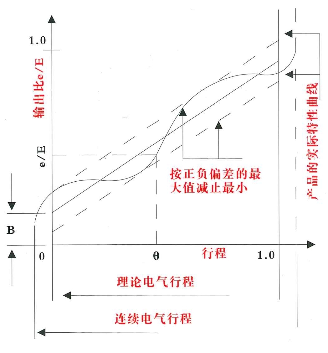
4.6-Independent Linearity
For non-linear functions, segmented linearity is often used to describe their independent linearity. The maximum deviation from the actual function characteristic of a reference line with slope and intercept is minimized, represented as a percentage of the total applied voltage, and its value is determined over the specified theoretical electrical travel.
4.7_Absolute Linearity:
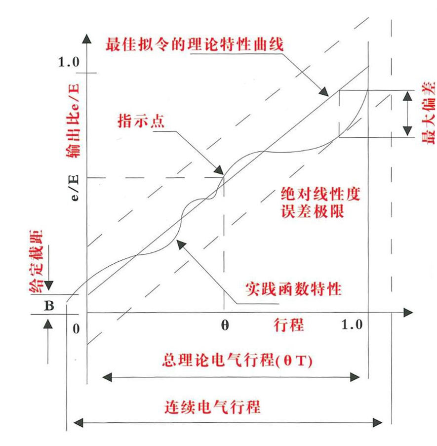
This value is more stringent than independent linearity because it represents the maximum deviation between the actual function and all defined reference lines, expressed as a percentage of the total voltage, measured over the theoretical electrical travel, and it requires an actual output index point.
The reference value line can be fully defined, i.e., the low-end and high-end output rates are separated by the theoretical electrical travel.(Theoretically). Unless otherwise specified, these end output rates are 0.0 and 1.0, respectively.
Mathematical Expression:E0/E1=A(0/0T)+B+/-C
Where A is the given slope; B is the given intercept when = 00, unless otherwise specified: A = 1, B = 0.
4.8-Lifespan:
Refers to the number of times the potentiometer's rotation and the defined decay characteristics are allowed within the specified parameter limits under normal operating conditions and linear sliding.
4.9-Resolution:
The sensitivity of the potentiometer to achieve output rate measurement.
4.10-Repeatability:
After rotating or sliding several turns, the maximum change in the potentiometer at the same position according to the theoretical electrical index, expressed as a percentage of the total voltage.
4.11-Travel:
4.11.1-Theoretical Electrical Travel:TET
Under the conditions of adhering to the theoretical function and its related consistency restrictions, the specific shaft travel.
4.11.2-Actual Electrical Travel:AET
The total travel between the two points where the measurable output rate change occurs between the first and last points.
4.11.3-Mechanical Travel:MT
Refers to the travel of the shaft between the stop points, for sensors without stop positions, the mechanical travel is continuous.(Only applicable to rotary sensors).
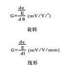
4.12-Gradient:
The rate of change of output relative to the shaft travel.
4.13-Index Point:
A reference point set to specify the relationship between the shaft and the output rate, used for referencing the shaft position.
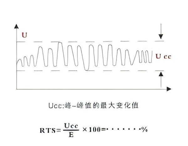
4.14-Output Smoothness:
Is a reaction to the output input being out of sync, output smoothness includes the effects of contact resistance changes, resolution, and other micro-nonlinear outputs.
4.15-End Voltage:
Refers to the voltage between the slider and the starting end when the shaft is pointed at the corresponding end of the electrical continuous travel, expressed as a percentage of the total voltage.
4.16-Voltage Divider:
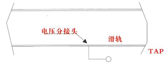
It is a resistive electronic junction that does not affect the output characteristic and typically has good impedance; it may not be able to carry the rated current. The voltage divider is located on the slide rail and the total applied voltage; it is usually located in the middle of the TET (Theoretical Electrical Travel).
4.17-Current Divider:
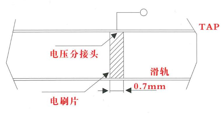
Connected to a resistive element, it can carry the rated current and may affect the output characteristics.
4.18-Initial torque:
The force distance at which the shaft begins to rotate clockwise or counterclockwise during mechanical travel
4.19-Rotation distance:
The total rotational force distance of the sensor shaft.